A better Real Time Clock
A better Real Time Clock
The DS3231 RTC is much more suited to the micro:bit than the DS1302. That's because it is designed to work with 3V devices (the DS1302 backup wasn't very reliable at 3V).
Here are a few reasons why you might want "real" time on a microbit:
- if you are recording measurements (data logging) you probably want to record the time you made them - this is known as a timestamp.
- if you are automating something, such as a security light, you might need to do things at a particular time.
The microbit can measure elapsed time, which can be useful, but you need to know the date and time when you started the timer.
You can use the data logging feature in MakeCode's editor but that (at the moment) doesn't make a timestamp, and your microbit would have to be connected to a computer running MakeCode.
I want to run data logging without connecting to a computer, so that the microbit is a self-contained module. So adding a small Real Time Clock module solves the problem. I can upload measurements, with their timestamps, from the microbit, once a day or once a week, for example.
The DS3231 also has a few interesting features:
- It has 2 alarms
- It has a temperature sensor - accurate to +/- 3C
This project uses the HW-84 RTC module which is widely available on eBay etc. It includes a small battery too, so you won't have to set up the time if the microbit's power gets disconnected.
Connecting the HW-84 RTC to the microbit
The microbit communicates with the RTC module using the I2C (inter-integrated circuit) protocol. This uses 2 wires for data (SDA and SCL) and two for power (VCC and GND). We need to connect them as follows:
GND to GND
VCC on RTC to 3V on microbit
SDA to SDA (pin 20 on microbit)
SCL to SCL (pin 19 on microbit)
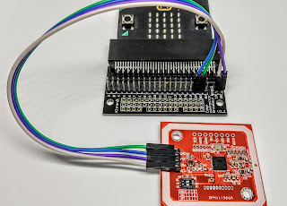
You can use the SQW pin on the HW-84 to tell the micro:bit when an alarm has been triggered. You could do this by connecting SQW to P0 of the micro:bit
The photo shows the wiring, using an expansion board on the micro:bit - it also shows a pull-up resistor between P0 and VCC:
 |
| HW-84 RTC board connections |
 |
| microbit connections |
Testing the RTC
There is a set of MakeCode blocks for the DS3231, the chip that is used in the RTC. In MakeCode, click on Advanced and then scroll down to Extensions. Search for DS3231 and click on this icon:

The first thing to do is to set the date and time. I used 2 blocks of code:
- on start, I showed a "sleepy" icon
- then, on button A pressed, we have a sequence of RTC commands that set the date and time and a smiley face icon:


Note that the RTC stores the date as both the weekday (1 to 7) and date in the month. The weekday number can start on whatever day you want.
Finally, we have some code that will send the timestamp to a computer over USB every 10 seconds.

This is the result I get using Beagle Term (an Android app) to display the microbit USB output:

Making a temperature logger
To show how we can add a timestamp to measurements, here is some code that uses the microbit's own temperature sensor and the RTC's built-in temperature sensor. In this example I have formatted the date to show just month and day. 

This is some typical output:

Note! the temperature(upper) function is formatted as a "Two's complement" number. If you want to display negative temperatures correctly you will need to add some code to do the conversion.
Using the alarms
Here's an example of using an alarm to run a bit of code every hour. Our main code needs to be alerted when the alarm goes. The DS3231 can send an alert on the (not)INT pin (which is labelled SQW on the board - because it can also be used to send out a square wave). The SQW pin goes low when the alarm time is reached, and it stays low until we clear the alarm flag.
In many computer systems the alert is done with an interrupt - a signal which stops the main code doing what it was doing. I found that this wasn't easy to do with a microbit, so I opted for the main code to poll the P0 pin every (say) 10 seconds. This still leaves plenty of time for the main code to do other things.
When it detects that P0 is low and that the A1 alarm flag is set then we can make a measurement.
I connected the SQW pin of the RTC board to P0 of the microbit (see photos in the Connecting section above). Note that this wire needs a pull-up resistor - the microbit can provide a weak on-chip pull-up resistor; for convenience in testing I used a separate 5k1 resistor.
Setting the alarm time
We need a code block to set the alarm time and mode:

- We are using the A1 alarm, in minute mode - it should trigger every hour when the minute counter reaches 40.
- Some initialisation is done - resetting both alarm flags at the beginning, and enabling the interrupt for A1.
- We could also use A2 for some other purpose.
The polling loop
This loop tests the microbit's P0 pin and the DS3231's status every 10s.
If the conditions are met then we log a temperature measurement - in this case we send the date/time stamp and temperature values to USB:

Here is some output on the USB:

Ideally, for an application such as weather measurements, we would store a number of readings on the microbit before sending them on to another computer for analysis.


Comments
Post a Comment