Low-cost solar power source for microbits
 |
| Solar panel, microbit, battery and regulator |
Update
I have made a few improvements since this post was published in September 2022:
- The key change is to use a separate low-dropout regulator (LDO) to provide the 3.3V supply to the microbit and other components. I had previously used the microbit's internal regulator. I found subsequently that it has a curious high-current region as the battery voltage drops, which leads to a period of rapid battery discharge.
- AA rechargeable cells, with 1200 mAh capacity, replace the previous AAA 850 mAh cells
- I use a 2W solar panel and a smaller current limit resistor, so that I can get a higher charging current
- I added a PNP transistor to the output of the TL431 shunt, so that it can handle more than 100 mA
Introduction
This article describes a low-cost DIY solar power source which is aimed at school projects such as weather stations, Typically you want to log readings from sensors every hour or so, upload them now and again to a computer, and then produce charts to analyse your data.
I’ve been building microbit-based weather stations for a while, and the power source has always been a problem. Conventional dry cells are expensive and will require replacing if you want to record the weather over more than a week or so.
So a rechargeable battery which can be topped up from a solar panel is attractive. Ideally it would sit out in all weathers and charge during the daytime! And it wouldn’t cost too much for, say, schools to buy or build.
I experimented with LiPo (Lithium-ion Polymer) batteries which are used in so many devices now. But they do require quite careful charging control and are not especially cheap. A better solution seems to be NiMh (Nickel-Metal hydride) cells. A battery made from 3 cells in series will deliver between about 3.0 and 3.9V, which is then regulated with a tiny LDO device, to limit the maximum voltage at the microbit's 3V input. I used an AA cell with 1200 mAh capacity.
Ideas from the web
There are many articles on the web, and these two were handy for making a start on the design:
Design and test
My design choices came down to:
Solar panel: 6V, 2W - so at peak power it could deliver over 300 mA. However in this design we limit the panel voltage to about 4.5V which in turn reduces the available current, In practice the peak current I get is about 150 mA.
Battery: 3 NiMh 1200 mAh cells in series.
Regulator: home-made - see schematic below.
To test this I wrote a program to run on the microbit which will measure several voltages in the power path every 15 minutes. The test code uses an ADS1115 ADC which connects to the microbit over the I2C bus, together with a DS3231 RTC (Real Time Clock). A weather station project would typically consume less than this project (about 15 mA).
The program logs the readings in the microbit's memory; the readings can be uploaded in a batch via radio to another microbit which is connected to a device (such as an Android phone) over a USB cable.
Schematics
.png) |
| Regulator |
The charge current control consists of the Schottky (low-drop) diode D1 in series with resistor R1, which sets the maximum charging current to about 200 mA.
A TL431A shunt regulator prevents the battery voltage from rising too high. When the voltage at pin Ref exceeds the internal reference voltage of 2.5V the Cath pin starts sinking current. The battery voltage is scaled, at Ref, by a factor depending on the setting of the potentiometer R2. R2 is adjusted to give a maximum battery voltage of 4.2V. Note that this limit needs to be high enough to ensure you charge the battery enough to see you through dark days, but not too high to reduce the battery life.
Here are some readings from 6am to 6pm on a reasonably sunny winter day:
 |
| 6am to 6pm readings |
The battery charged to its limit voltage over a couple of hours, and the charging current reached a peak of 150 mA.
During the previous night the battery voltage reduced from 4.009 to 3.841V:
.png) |
| 6pm to 6am readings |
The TL431A device is rated at 100 mA, and we need to be able to shunt more than that. A PNP transistor Q1 provides a higher current path. Note that Q1 can dissipate quite a lot of power in strong sunlight, perhaps as much as 1W, so an adequate device package and/or heat sinking should be used.
I used a MCP1700 3.3V LDO to convert the battery voltage to 3.3V maximum.
The 4 ADC channels are used to measure:
ADC0 = solar panel voltage
ADC1 = positive end of R1, the charging resistor
ADC2 = negative end of R1, which is the battery and USB supply input to the microbit
ADC3 = 3V regulated output of the microbit
.png) |
| Attenuator |
 |
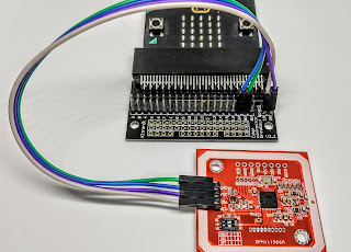
| Microbit, ADC and RTC |
Putting it together
 |
| Test hardware |
 |
| Solar panel |
Radio link
 |
| Radio link |

During daylight the solar panel voltage is about 4.5V, and the charge current is about 70 mA.
- rt - read date and time
- st - set time (e.g. st0359)
- sd - set date (e.g. sd21062022)
- up
- xx - delete all stored readings

Program notes
Results
- (top) the solar panel voltage (Vpanel) and battery voltage (Vbat)
- approximate charging current in mA
- charge, in mAh, added to the battery per day

- The panel voltage doesn't quite get up to 6V, but it is winter! And, for these tests, the panel was indoors and not optimally aimed at the sun.
- The battery voltage limits at about 4.2V
- To maintain the battery level over a long period, a charge of 400-500 mAh is required per day. This implies that the circuit is consuming around 15 mA.
- Under continued low-light conditions the battery voltage will get too low for the microbit and other components to operate. But when conditions improve the battery will start to charge again.
- I have found occasions when the microbit does not restart its program, until VDD is momentarily disconnected. Some kind of forced reset may be useful.
- With the existing data logging code, where the readings are stored in the microbits volatile memory, the readings will be lost when the power is lost. A good solution to that is to use a WiFi/internet interface to do the data logging in real time - see Microbit WiFi weather station, for example.
- I recommend using a higher power PNP transistor for Q1 in the regulator, such as the TIP32C. This will allow it to shunt high current more reliably.

Comments
Post a Comment