A compass project for the micro:bit
A Compass project for the micro:bit
In this project, we use a micro:bit and Makecode (https://makecode.microbit.org/) to measure compass “bearing” or angle - like a magnetic compass does.
We usually think of North as 0 degrees and go round clockwise. There are 360 degrees in a circle. East is a quarter of the way around the circle, so East is 90 degrees (because 360 ÷ 4 = 90), South is 180 degrees, and West is 270 degrees.
Calibration
The micro:bit has a built-in compass and it needs to be calibrated (or “adjusted” in other words) before it is used.
When you run the code the screen will display “TILT TO FILL SCREEN”, and you will see some dots on the screen, like this:
 |
| Calibration step |
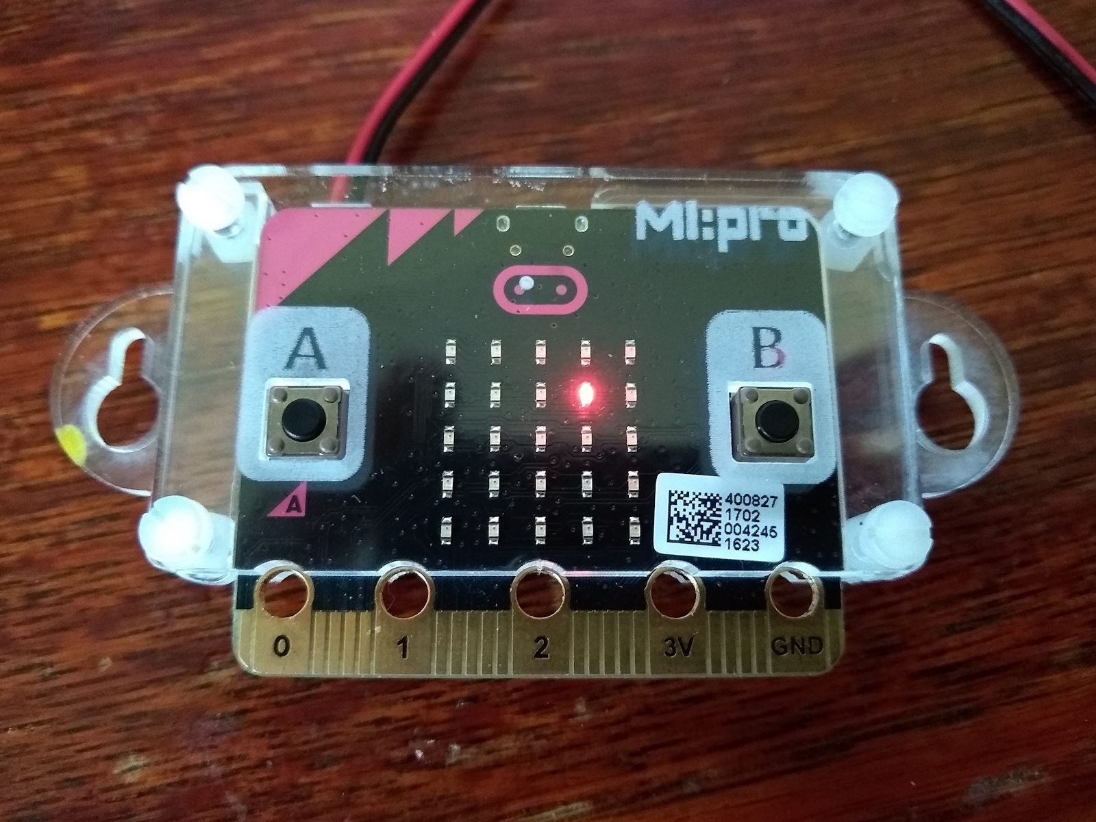
When you have filled the screen by doing the tilting, you will get a smiley face, and your own code will run.
Code
Here’s the code to show a dot on the screen at N, NE, E, SE, S, SW, W and NW (that’s every 45 degrees) and so on, depending on which direction your micro:bit is pointing. You can change the code if you want.
The code does the following steps, forever:
- It reads the compass heading input and stores it in a variable called angle
- It compares this with the angle for NE - if it’s less than 45 degrees then it shows the led pattern with a dot at the top of the screen
There are lots of the if and else if blocks in the code, so the picture below has them arranged in separate strips!


Test your code
You can test the code in the makecode simulator by dragging the little pointer round:
 |
| Simulator snapshot |
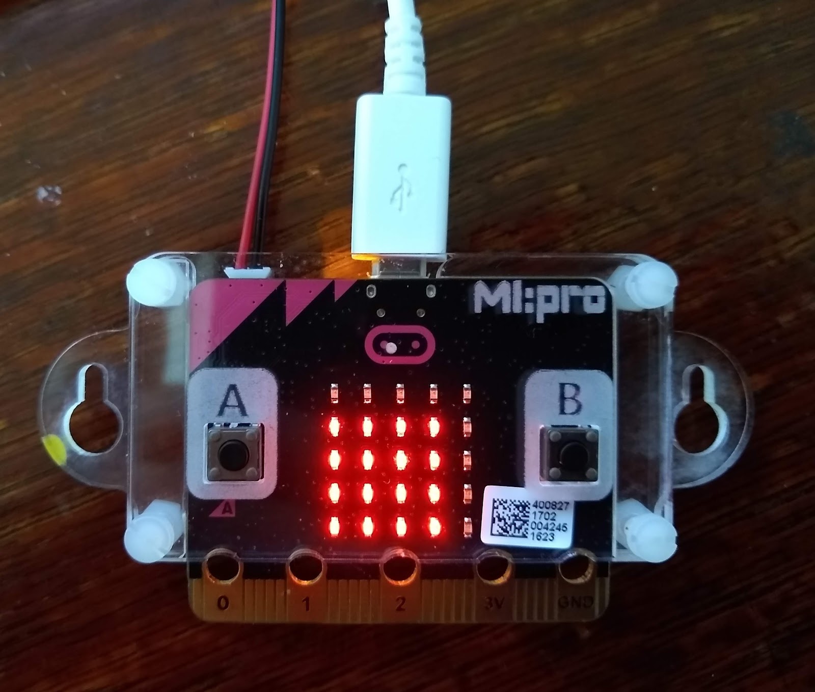
Testing on a real micro:bit
When you try it on a real micro:bit you will see the single dot move as you move around:
 |
| I'm pointing North East! |
Just for fun!
I wasn’t very happy with the code - it’s quite long because we have a separate show leds block for every point. Just imagine if we wanted to display 16 points instead of 8!
So I thought of a way to make the code smaller, and also it might be easier to increase the number of points we want to display.
Here is how my code works.
It uses the makecode block plot x y - this is another way to light up one LED on the display. You tell the micro:bit which LED to light up using its x and y positions.
The x and y numbering is shown as x, y in the diagram below:
 |
| x and y numbering |
I have coloured in the 8 LEDs that we are using for the compass points.
Then we can give our LEDs a number each, from 0 to 7. I called this number point (like a point of the compass):
 |
| Our LED points |
We find out point by dividing angle by 45 and then using floor :

floor is just a way of getting the lowest whole number less than something. So, for example, floor of 3.2 is 3.
Next, we can calculate the x position and y position of the LED to be lit up, using the value of point.
This is easier to do if you draw a table showing point and the x and y positions. I have made variables for these, called xled and yled.
angle point xled yled 0 to 44 0 2 0 45 to 89 1 3 1 90 to 134 2 4 2 135 to 179 3 3 3 180 to 244 4 2 4 225 to 269 5 1 3 270 to 314 6 0 2 315 to 359 7 1 1
Now you can work out a formula for xled and yled, using point.
I used these formulas:
- If point is 0 or 1 or 2 then xled = point + 2
- If point is 3 or 4 or 5 or 6 then xled = 6 - point
- If point is 7 then xled = 1
- If point is 0 or 1 or 2 or 3 or 4 then yled = point
- If point is 5 or 6 or 7 then yled = point - 2
Then I used makecode blocks to code those formulas:

At the end of the code I used a clear screen block before the plot x y, to turn off the previous LED.
There may be other ways to code this up - have a go yourself!


Comments
Post a Comment