Microbit ADC Logger
Introduction
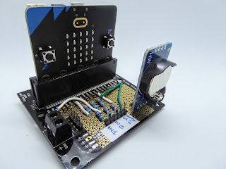
This is a simple data logger that reads and logs the voltage on the microbit pins P0, P1 and P2 every hour. It stores the reading as a text string together with the date and time of each reading.
The date/time is kept by a DS3231 Real Time Clock (RTC) board.
The readings can be uploaded to a device using the microbit’s USB.
An example reading:
#count = 3
17/06/2022 11:00,3.28,0,0
17/06/2022 12:00,3.28,0,0
17/06/2022 13:00,3.28,0,0
To allow the measured voltages to be greater than the nominal supply microbit voltage (3.3V) two external resistors are used to divide the measured voltage so that the pin voltage V(Pn) does not exceed 3.3V.
The scaling in the code assumes external resistors of 270 kΩ from input to Pn and 330 kΩ from Pn to ground. So full scale is 6.0V. Other ratios require code change.
The ADC voltage reference is the microbit “3V” supply (nominally 3.3V), so if the supply drops below this then the ADC readings will be wrong. It is possible to change the ADC reference to be relatively independent of the supply voltage, but that is outside the scope of this document.
The readings are averaged over a programmable number of measurements. The code has this number (Nave) set to 10; you can change it.
| Circuit diagram Usage Readings can be uploaded to a terminal application, such as the Android app “Serial USB Terminal”, by pressing button A. An instant reading can be shown on the microbit displayed by pressing button B. Further interaction can be obtained by sending a 2-letter command and possibly data via USB to the microbit:
Code The microbit code (Blocks and JavaScript) can be downloaded from Github. |


Comments
Post a Comment