Microbit with an external ADC
Update 4 Sept 2022:
I found that the ADS1115 code below works fine when you are reading one channel. But when you are reading more than one channel (i.e. switching from one to the other) you can easily get a wrong reading.
The reason behind this is described on a TI forum here. Briefly, you need to have a delay between setting the ADC channel and reading the conversion result.
I have written an unpublished MakeCode extension which adds simple blocks and handles this delay. It can be used by pasting its Github location into the MakeCode Editor's "add extensions" search bar.
Introduction
This post shows how you can connect up a low-cost external ADC to a microbit using the I2C bus. The ADS1115 ADC has 4 channels and an on-chip voltage reference. Example code is provided for Micropython and MakeCode/JavaScript.
Background
The microbit includes an ADC, but it has limited usefulness for measuring voltages - particularly if you want to monitor the microbit's supply voltage. I'm doing that as part of some experiments with solar powering microbits for schools.
Although the microbit's internal Nordic microcontroller does have a voltage reference, the default microbit configuration is for the ADC to use the supply voltage as the reference! So if you want to measure VDD it will always be "full scale", or 1023 in decimal.
There is a way round this limitation (if you only want to measure VDD) which uses a few low-cost components - just connect an external reference voltage to an ADC input and do some arithmetic. Here's a diagram and some code:
 |
| Voltage reference schematic |
This particular reference diode generates 1.25V but you can select other values if needed. The other component values are not critical.
The formula for the 10-bit ADC output N is:
N = 1023 * V(P0)/VDD
So VDD = 1023/N * 1.25
This can be coded very simply on a microbit using MakeCode:

Here I have swept the microbit's VDD supply, at the 3V pin, from a point where it is just operating (slightly below 2V) to the maximum specified voltage. Here are some measurements:

%20vs%20VDD%20(Meter).png) |
| Graph of measured VDD voltage |
There are limits to the accuracy of all the tools used but we can see that the microbit's on-chip ADC is useful for this particular measurement.
Another method
I have seen other schemes, such as this, where you can write some Python code to reconfigure the Nordic microcontroller to use its internal voltage reference. This at least would allow you to measure any voltage (not just VDD). Ideally you could write a MakeCode extension (using C++) which would make the changes. But it is a bit complex because the V1 and V2 microbits have different internal microcontrollers with different registers and so on. The tools for coding are also different for V1 and V2. And C++ coding is not a happy place for me. I've put that on the back burner for now!
An I2C ADC
The I2C bus is quite well supported by the microbit, and it's quite easy to connect up devices such as RTCs (Real Time Clocks) and so on, especially if someone has written a MakeCode extension to make it easy.
I chose the ADS1115 16-bit ADC which is reasonably low-cost, and a small board can be bought which is easy to hook up, from Hobby Components in the UK, for example. It comes in several variants (ADS111X) and there is also a 12-bit version (ADS1015).
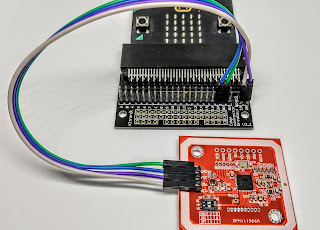
Here is my test setup - the potentiometer allows the voltage at the ADC's A0 pin to be swept between 0V and VDD:
 |
| The ADC mounted on a prototyping board |
 |
| Circuit diagram |
Code
I couldn't find a MakeCode extension for the ADC, so the code had to be written from scratch (no pun intended). I started with Micropython as this is quite quick to experiment with, and later transferred the code to run on MakeCode's JavaScript and Blocks.
Update 4 Sep 2022: I wrote an unpublished MakeCode extension which adds simple blocks and handles a delay to remove channel-switching errors. It can be used by pasting its Github location into the MakeCode Editor's "add extensions" search bar.
The starting point is the device's datasheet which is available from Texas Instruments. This does need careful reading; I got caught out by 2 requirements which were unusual, at least for me:
- Writing to the ADC's Configuration register requires a 3-byte write
- Reading data from the Conversion register requires a write to the Pointer register before each 2-byte Read
These requirements are covered in the Quickstart Guide part of the datasheet.
MakeCode/JavaScript
MakeCode doesn't provide a 3-byte I2C write, so we have to create a function to do that (ic2write3). Also there are no blocks for bitwise logic (useful for setting up the configuration register). You can write the code using JavaScript bitwise operators, as I have done for configHi. If you switch to Blocks mode then MakeCode does a good job of showing the code:
 |
| Showing JavaScript in Blocks mode |
function i2cWrite3 (addr: number, num0: number, num1: number, num2: number) {
let buf = pins.createBuffer(3)
buf[0] = num0
buf[1] = num1
buf[2] = num2
pins.i2cWriteBuffer(addr, buf)
}
let result = 0
let CONFIG = 1
// slave address of the ADC
let ADCaddress = 72
// starts conversion
let OS = 1
// single-ended mode, AIN0 and GND
let MUX = 4
// 1 = +/- 4.096V FSR
let PGA = 1
// counts per volt
let SCALE = 8000
// Single shot mode
let MODE = 1
// Disable the comparator
let DIS = 3
let configHi = OS<<7 | MUX<< 4 | PGA<<1 | MODE
let configLo = DIS
loops.everyInterval(1000, function () {
let CONVERSION = 0
i2cWrite3(ADCaddress, CONFIG, configHi, configLo)
pins.i2cWriteNumber(
ADCaddress,
CONVERSION,
NumberFormat.Int8LE,
false
)
result = pins.i2cReadNumber(ADCaddress, NumberFormat.Int16BE, false)
serial.writeLine("reading = " + result)
serial.writeLine("voltage = " + result / SCALE)
basic.showNumber(result / SCALE)
})
Micropython


Comments
Post a Comment