Air Quality Monitor
Sensing air quality by measuring the concentration of 2.5 μm particulates is a useful and fun thing to do. This project displays the measurement on a microbit, and it will be developed to also use a small LCD module.
This is slightly more advanced than my usual microbit projects - it uses JavaScript rather than blocks, and involves some fiddly soldering.
The inspiration comes from some fascinating internet chat and articles on how to adapt a low-cost Ikea monitor, the Vindriktning. This cost £15 at the time of writing, which seems affordable for a school project. The device is a stand-alone small box, that has a simple LED indication to show green (good), yellow (ok), and red (not good). It's powered from a USB-C lead.

The website for Home Assistant (free software for home automation) has a useful series of posts on Vindriktning here. These have focussed on adding a small device to log the air quality measurements. They have generally used an ESP8266 microcontroller which is small enough to fit inside the Vindriktning's case and can log data to the internet via its WiFi.
I've decided to use a microbit (which won't fit inside!) but it is easier to code and has a built-in display. I want to add a small I2C display to the microbit in a future edition of this blog. The microbit can log the data for readout via radio, as I have done in the past for a weather station.

How do we read the PM2.5 measurements?
The Vindriktning contains a PM1006 sensor and small microcontroller; this sends a command to the sensor every few seconds, and the sensor then sends back its message on the 'REST' pin. The message consists of 20 bytes, sent over a serial interface at 9600 baud: each 8-bit byte is preceded by a start bit and followed by a stop bit. The bytes are transmitted with the least significant bit first - the MakeCode Serial data library takes care of that.
 |
| REST data format |
The first 3 bytes are a header which could be checked by the code. The data we need is in the bytes labelled DF3 and DF4
Building the hardware
 | ||||||||||
Level shifter schematic
The 5V and 0V pins on the Vindriktning are wired to the level shifter board, and also to the microbit's micro-USB connector. The microbit has an internal regulator which converts the 5V to 3V which we then wire to the level shifter board.
The connections to the Vindriktning "pins" need careful soldering - they are actually very small pads on the PCB
Code
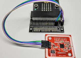
let num=0 let rxBytes: number[] = [] basic.forever(function () { //wait for received data from uart serial.redirect(SerialPin.P0,SerialPin.P1, BaudRate.BaudRate9600 ) serial.setRxBufferSize(20) //this resets the buffer let rxData = serial.readBuffer(20) //read up to 20 bytes serial.redirectToUSB() //log data in MakeCode's console for(let i=0; i<rxData.length; i++){ num = rxData.getNumber(NumberFormat.UInt8LE, i) rxBytes[i] = rxData.getNumber(NumberFormat.UInt8LE, i) } let pm25 = rxBytes[5] << 8 | rxBytes[6] basic.showNumber(pm25) basic.pause(2000) }) Initial testsThe photo below shows the Vindriktning, level shifter, and microbit connected together for testing. Note that the microbit is temporarily powered from my computer, as the USB is used for downloading code and uploading debug messages. Once complete we will power the microbit from the Vindriktning's 5V pin, via a micro-USB plug.
|


 |
| Testing the assembly |

 |
| The final assembly - on top of the Vindriktning |


Comments
Post a Comment