Rain gauge 2
Update: I've added a chart showing an actual day's recording.
A while ago I made a rain gauge based on measuring the resistance of rainwater.
This is an improved version: it should be more accurate because it measures the weight of the water collected in a tank over a given time. The weight can be converted to the depth of rain falling in a given period by simple arithmetic.
The diagram below shows the scheme - rain enters the tank which is weighed periodically. When the tank is "nearly" full it is emptied, and the scales are reset.
 |
| The overall arrangement |
Lengthy experiments with an electrically operated water valve were not successful! But a submersible pump does work quite well; provided the water tank side wall is quite low we can keep the settling time short.
We are using an electronically controlled pump. So no manual intervention is needed, and we should be able to have an unattended rain gauge! Ideally the process of emptying the tank should be done very quickly so that we minimise any error if it is raining at the time.
With the 5 V pump and 7 mm tubes I am using, we can empty 0.36 litres in less than 20 seconds. I would like the process to be quicker; that would probably need bigger diameter tubes and a bigger pump, which in turn would need a higher voltage.
Features
- Powered from a single 5V supply via a USB cable
- Readings of weight are stored on the microbit
- Readings are uploaded using Bluetooth (when a device is connected), giving essentially unattended operation
- The device (e.g. laptop, phone) is used to convert weight to depth of rain that has fallen (based on the area of the input funnel mouth)
- The depth readings can later be presented as rainfall per day or hour, for example
- The tank is emptied automatically when the weight reaches a preset level, to a tube on the underside of the gauge's box.
- We can use serial 2-way data and commands for debug over USB
- A Real Time Clock (RTC) allows us to "date stamp" readings
- Easy coding using MakeCode blocks or JavaScript
- Makes use of 3D-printed "plumbing" parts
Initial experiments
You can build a weighing instrument from some basic parts:
- a platform to put the load on
- a load cell, which is defined as a transducer which converts force into a measurable electrical output. In this case it converts platform movement into a very small change of electrical voltage.
- an Analogue-to-Digital converter (ADC)
- a microcontroller
I chose an easy way to start with - I bought this bit of kit from Amazon: "Innovateking-EU Digital Load Cell Weight Sensor HX711 AD Converter Breakout Module"
It combines the platform, load cell, and ADC (a specialised device which goes by the name
HX711). All you have to do is add a microcontroller and some code!
I'm using a BBC V2 microbit for the microcontroller, and MakeCode for coding in blocks. Fortunately there is a MakeCode extension (library) for the HX711 ADC. The HX711 module needs 4 connections to the microbit:
- VCC and GND
- DT - data output from the HX711 module to the microbit
- SCK - clock from microbit to HX711 module
Here are some photos of the load cell and HX711 module:
 |
| The platform, load cell and ADC |
 |
| Another view |
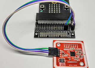
Here are the microbit connections:
 |
| Microbit connections |
Experiments with this setup showed that the microbit worked well with the load cell and HX711. So I progressed to develop the physical components and the code.
System overview
Electrical circuit
The schematic below shows the main electronic parts of the system - I have added them to the same prototype board used on my
Microbit weather station which includes a Real Time Clock (RTC).
The new items are:
- the HX711 module pins,
- a pull-down resistor on the DT pin (very important),
- a pin from the microbit's P8 pin to a new pump board,
- a filter (C1, L1, and C2) to try and reduce supply noise to the HX711
 |
| Schematic (excluding pump control) |
Filtering "noisy" readings
The HX711 is a very sensitive ADC, and USB chargers vary in the amount of noise they generate. I found that the HX711 can give sporadic erroneous readings, and if they are big enough it would cause the pump to turn on when it wasn't needed.I've used several approaches to overcome this problem:
- I switched to the Sparkfun SEN-13879 HX711 board. This has a separate VCC (5V) supply pin which means that the supply should not be too noisy
- I've added some persistence checking in the code:
- when I detect a significant change of weight I then immediately make a new weight reading
- if this is (nearly) the same as the previous reading then it's a genuine reading, so it gets stored
- otherwise the reading isn't stored.
Pump control
The pump motor requires a current of about 100 mA at 5 V, and this means we need a power transistor to switch the current on and off. A good one is the TIP120. This can be controlled by a 3V signal from the microbit - I'm using the microbit's P8 pin.
 |
| Pump control schematic |
Notice that there is a diode across the DC motor to protect the transistor from over-voltage when the motor switches off. Also I have an LED to show me when the pump is on - useful for debugging!
Power supply
We use a 5V supply for the pump and we can split a single USB charger lead into two, so that one supply feeds the microbit and the other feeds the pump driver. Here's a suitable splitter:
 |
| USB splitter |
Its input is a single micro USB cable from a computer or charger and it has two outputs. The shorter output cable supplies only power, so I use that one for the pump; the longer cable handles both power and data, and I use that for the microbit. That means I can download new code from the computer, and send back serial messages to debug the code.
The physical components
The physical parts are as just as important as the electronics and microbit code. Some of these, such as my rain collection tank and the pump, are "off the shelf". Others were not readily available, and a friend used 3D printing to create those parts (a U-tube, a tank holder, and the exit funnel).
 |
| Components, mounted on the board |
 |
| Pump control, HX711 board, and microbit |
The board is mounted in a weatherproof plastic box, with the water exiting through a plastic tube in the base.
Microbit code
The code is quite simple really - we just make a weight measurement every now and again (I chose once a minute). The rest of the code deals with:
- emptying the tank when it gets to some level (I'm using 300 g)
- sending weight measurements and key events over serial USB link on a regular basis (every minute)
- storing weight measurements and key events on the microbit - but only when there is a significant change on the weight
- uploading the stored readings via Bluetooth when a connection is made
- responding to commands sent via USB - see below.
First, a note about the user interface. I want the rain gauge to operate remotely, connected only to power via a USB cable. So the data upload is done through Bluetooth. But for debug and initial setup (such as setting the RTC's date and time) it is sensible to use the microbit's USB serial interface. Then we can connect a terminal app and have two-way communication. We can send other commands to read the date and time, for example.
The table below shows the command set I've used for the serial interface.
 |
| USB serial commands |
Bluetooth link
You will need to
pair your microbit and device before using them.
Here is a set of instructions for doing the pairing for an Android device.
Emptying the tank
The small aquarium pump I use can empty the tank very quickly, so I decided to switch it on for a fixed time (20 seconds), wait for a short time for the water to settle, then do a "tare" operation with the HX711. This simply zeroes the weight reading, so that we restart from a known zero level.
The pump doesn't empty the tank completely (because its intake is slightly above the tank floor). That won't matter much, unless the water that's left there evaporates. That will lead to an error, which can be compensated via the code.
Code
I'm using Microsoft MakeCode, and several extensions are required:
- HX711 - the ADC
- Bluetooth - to upload stored readings to a device, eg computer
- DS3231 - real time clock
The complete code for the project is available on Github
here. but an example, the weight-reading loop, is shown below:
 |
| Weight reading loop |
The HX711 can give sporadic erroneous readings, so the loop includes some filtering to reject them. This consists of checking by reading again after a significant change in weight; if the second reading is close to the first reading then it is assumed to be correct and so it is stored.
Event logging (for debugging) is done by sending messages with a date and time stamp to the serial port. These messages are also stored on the microbit's arrays so that they can be read out via a Bluetooth link.
Example output
 |
| Stored readings |
This screenshot, of stored readings over USB, shows a typical sequence as the tank fills and is then emptied. Notice the erroneous tare reading at 10:01 - this can be handled in the device software after uploading.
Footnote on weight measurement
I mentioned that the load cell converts the force (or weight) on the platform to an analogue voltage. The ADC (the HX711 module) converts this voltage to a digital number. Let's call that number D.
We can calibrate the system by putting:
- zero weight on the platform, then noting D - let's call the number offset.
- a known weight W on the platform, and again noting D. Let's call that number Dw.
Then, assuming the system is linear (which seems reasonable), we can convert our Dw number to weight W using this formula:
W = (Dw - offset)/scale
From this we can calculate scale.
Here are some measurements I made:
offset = 8481274
W = 315 g
Dw = 8611574
So scale = (8611574 - 8481274)/315
= 413
We will need the values of offset and scale in the final code; we can write some code to make that quite easy.
Calibration code
We start by having no weight on the platform; when the display tells us to start we place our known weight W on the platform.
The microbit then displays the calculated weight via the serial port, in a continuous loop. Press button A to increase the reading, or B to reduce it, until the displayed weight matches the actual weight.
Here is some code to do this (you need to load the extension HX711 before coding):
 |
| Calibration code |
The
on start block assigns microbit pins to the HX711 Data and Clock signals, then it reads the zero-weight number and stores it in the HX711's
offset. The code also sets a starting point for the HX711's
scale.
We either decrement or increment
scale each time we press button A or B.
The main forever loop simply displays the weight with, crucially, a limited number of decimal places! It also displays the scale value which you will need later on. Here's an example:
 |
| Example display |
Footnote on flooding
How much rain can fall in a certain time? The table below was supplied by the UK's Environment Agency.
So the highest reliable rate (from 1953) is about 1.3 mm/minute.
For a funnel of 150mm dia (so area = 17671 mm^2) that is nearly 23,000 mm^3 in 1 minute, or 23 ml which weighs about 23 g.
My pump will empty about 300 g in 20 s, so it should cope.
Field testing
Here's a first go at recording outside, in real weather!
 |
| Chart |
And what the setup looks like - it could do with some protection from sunlight to reduce evaporation.

Further testing on 27-29 Sep 2021 during heavy rain - it worked well except for one occasion when the automatic tank emptying failed (it worked many times very well). I need to look at the code, and probably add a belt-and-braces spout!


Comments
Post a Comment